Additive Manufacturing

A (3-week long) third year project done in pairs as the prarctical activity augmenting our Additive Manufacturing module.
The Aim
We had to design one or two small parts to be manufactured through the FDM (Fused Deposition Modelling) process. The project would give us insight into some of the the parameters that govern the quality of parts produced through FDM and some of the challenges that 3D printing presents.


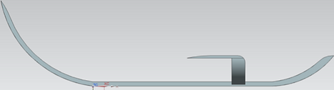
A non-functional glider CAD model was made using NX. To go along with it, a stand was designed to prop it up. Designing the glider was my responsibility, while my project partner did the stand.


The .prt CAD files were then exported as two separate STL files. These files are then loaded into Cura, a free software package provided by Ulitmaker for easy setup of builds to be done in their machines. Using Cura, parameters like shell thickness, fill density, print speed, travel speed, support types and more were defined.
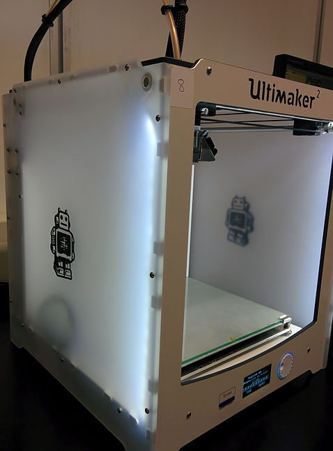
The parts would be made in the Ultimaker 2 Fused Filament Fabrication 3D printer. This was equipped with a 400 micron nozzle, a heated glass build plate, and a PLA (Polylactic Acid) filament feed.
The extruder head moves in the X- and Y-axis while the build plate moves in the Z-axis.

Parameters Used
Layer thickness: 0.06 mm
Shell thickness: 0.8 mm
Fill Density: 75% (being a non-functional model, strength was prioritised over lightness)
Print Speed: 50 mm/s
Travel Speed: 80 mm/s
Bottom layer: 10 mm/s (slower to allow it to stick to build plate)
Infill speed: 60 mm/s
Outer Shell speed: 10 mm/s (slower for higher quality)
Inner Shell: 40 mm/s
Support Structure
Structure type: Grid
A Grid support structure allows removal in one piece, making it a quicker process to separate the part from the support structure.
Overhang for support: 60º
Any face of the part that was 60º or less from the horizontal would require a support structure underneath.

Unfortunately, our first build was not able to to be printed completely due to the nozzle clogging up while left overnight. In the above image the 75% density infill is visible in the wings of the glider, whereas the on the stand, the smoother finish of the outer shell is visible.

The grid structure used proved to be too strong in relation to our parts, and would not come off without threatening to break the actual part as well. The grid supports also hindered acces to some of the "brim" material (the ribbed-texture surface in the above image) making it difficult to remove.

For our second round, Line Supports were used. These are generally easier to break off, but can be time-consuming and tends to leave a very rough finish that would need significant finishing work.
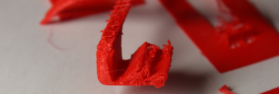


This time, with the print job having reached completion, the challenges with the material extrusion process were visible in the thinner parts of the model that were not printed the first time. These errors are likely due to the extremely thin elements where the errors occured. The layers being layed down for these parts likely didn't have enough time to cool down and solidify before the nozzle came back for the next layer and dragged the previous layer along as it deposited the new one.

To conclude...
Due to the limited amount of time and hence number of attempts, we weren't able to optimise parameters to fix the thinner parts of the model. To improve the final build, the time between printing layers for the thinner section would be increased, allowing the previous layer to solidify. Besides that, orienting the part nose-down would have reduce the amount of rough surfaces left over to smooth out in a separate process.